2013-11-30

Effective Cloner

I posted a custom transformer example here.
Advanced Geometric Operation: Divide a Line at Equal Interval

I thought that a loop is suitable to do that, but the iterative processing is not essential.
The Cloner transformer also does the trick.


I didn't notice such an effective usage of the Cloner.
Number of choices increased. Thanks, Gio. > Community: Road Chainage

2013-11-25

Poor Cat...

> Community: Leading zeros
Just a curiosity. How many ways are there to skin the cat?

1) StringFormatter + StringConcatenator
2) StringFormatter + AttributeCreator
3) StringPadder + StringConcatenator
4) StringPadder + AttributeCreator
5) StringConcatenator with @PadLeft function (FME String Functions)
6) AttributeCreator with @PadLeft function (FME String Functions)
7) AttributeCreator with Tcl command
8) ExpressionEvaluator with Tcl command
9) PythonCaller
10) TclCaller

At least 10 ways!

2013-11-24

Advanced Geometric Operation: Create Regular Polygons

=====
2013-11-25: Found a custom transformer example called RegularPolygonCreator, the approach is different from my example. FMEpedia > RegularPolygonCreator
=====
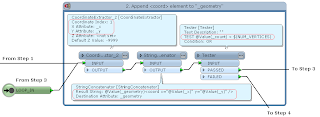
This custom transformer example transforms an input point into a regular polygon; number of vertices and radius of the resultant polygon are given through parameters.


The strategy is:
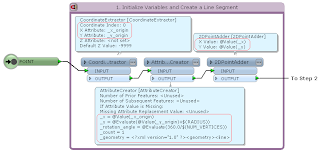
1) Create a line segment directing to north (positive direction of Y axis) from the input point; its length is equal to the given radius.
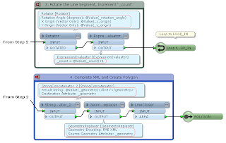
2) Rotate the line segment by specific angle (= 360 / number of vertices) repeatedly; get coordinate of its end node at each time, transform coordinate values into XML element (<coord x="x value" y="y value" />), and append it to XML fragment.
3) After appending all vertex elements, complete the XML, replace it with a line geometry, and transform the line into a polygon.

For example, the final XML for a triangle should be like this.
-----
<?xml version="1.0" ?>
<geometry>
  <line>
    <coord x="0" y="0.4" />
    <coord x="-0.346410161513776" y="-0.2" />
    <coord x="0.346410161513775" y="-0.2" />
  </line>
</geometry>
-----
This is in the "FME XML" encoding format, so it can be replaced with a line geometry using the GeometryReplacer transformer. Finally close the line to create a polygon using the LineCloser.


Originally, I needed to create radiational lines in an actual project. The example above is derived from that.
Radiational Lines:


=====
2015-10-16: A simpler way to create a regular N-gon.
(1) Create a circle area with the 2DEllipseReplacer.
(2) Stroke it with the ArcStroker.
Stroke By: Number of Interpolated Edges
Number of Interpolated Edges: <N>
That's it :)

=====
2013-11-25 Python example:
-----
import fmeobjects, math

class RegularPolygonReplacer(object):
    def __init__(self):
        pass
     
    def input(self, feature):
        if feature.getGeometryType() != fmeobjects.FME_GEOM_POINT:
            return
        n = int(feature.getAttribute('_num_vertices'))
        t = 2.0 * math.pi / n
        sin_t, cos_t = math.sin(t), math.cos(t)
     
        coords = [(0.0, float(feature.getAttribute('_radius')))]
        for i in range(n - 1):
            x, y = coords[i]
            coords.append((x * cos_t - y * sin_t, x * sin_t + y * cos_t))
        p = feature.getCoordinate(0)
        if feature.getDimension() == fmeobjects.FME_TWO_D:
            coords = [(p[0] + x, p[1] + y) for x, y in coords]
        else:
            coords = [(p[0] + x, p[1] + y, p[2]) for x, y in coords]
         
        # Create Radiational Lines
        coordSys = feature.getCoordSys()
        for q in coords:
            line = feature.cloneAttributes()
            line.setGeometry(fmeobjects.FMELine([p, q]))
            line.setCoordSys(coordSys)
            self.pyoutput(line)
     
        # Replace Point with Regular Polygon
        boundary = fmeobjects.FMELine(coords)
        feature.setGeometry(fmeobjects.FMEPolygon(boundary))
        self.pyoutput(feature)
     
    def close(self):
        pass
-----

2013-11-23

Effective BulkAttributeRenamer

This example is a part of an actual project I recently completed.
The source dataset contains fine mesh polygons covering a local government area; each polygon has land-use type code as an attribute named "lu_type", its value can be one of 12 different codes:
0100, 0200, 0500, 0600, 0700, 0901, 0902, 1000, 1100, 1400, 1500, 1600

The purpose is to clip the meshes by other polygons (representing some specific land lots), and create a table of every land-use sum area inside of each lot.
Columns of the destination table should be:
lot_id | A0100 | A0200 | A0500 | ... | A1600

Here, "Axxxx" means the sum area of a land-use type "xxxx" (0100, 0200, ...).

The workflow I created looks like this.


The point is the BulkAttributeRenamer parameter setting.
  Rename: Selected Attributes
  Selected Attributes: A
  Action: Add String Suffix
  String: @Value(lu_type)

In the AreaCalculator, I specified "A" to the Area Attribute name; then the value of "lu_type" (0100, 0200, and so on) is appended to "A" as suffix, in the BulkAttributeRenamer.
So, after exposing those attribute names (AttributeExposer), all land-use areas of a lot can be aggregated into a feature (Aggregator 2).

Result:


At first, I thought of using Python to rename the area attribute, but I just remembered this article. Community > Attribute renaming using attribute values
Wonderful BulkAttributeRenamer!

Use Case of Multiple Feature Attribute Support

Previous: Multiple Feature Attribute Support of the AttributeCreator in FME 2013 SP2

After that, I've come across some practical use cases:
Community > GroupBy functionality in ExpressionEvaluator
Community > pushing an attribute to variable or parameter then testing attributes against veraiable

Here, I'll give a simplified example for calculating cumulative total.
Assume every input feature has group identifier and a numeric value, like this.
_group | _value
1, 1
1, 2
1, 3
2, 4
2, 5
2, 6
2, 7
...

The goal is to append them the cumulative total of _value in each group.
_group | _value | _cumulative_total
1, 1, 1
1, 2, 3 (= 1 + 2)
1, 3, 6 (= 3 + 3)
2, 4, 4
2, 5, 9 (= 4 + 5)
2, 6, 15 (= 9 + 6)
2, 7, 22 (= 15 + 7)
...

That is, if the feature is the first one of a group, _cumulative_total should be equal to its own _value; otherwise should be sum of _cumulative_total of the previous feature and its own _value.

The AttributeCreator (FME 2013 SP2+) can do that easily.

There are two AttributeCreators in this workflow.
The 1st AttributeCreator creates an attribute named _cumulative_total, and initialize it by _value.
The 2nd AttributeCreator updates _cumulative_total using the "Multiple Feature Attribute Support" option and the "Conditional Value" setting.
If _group of the current feature is equal to _group of the previous feature, it sums _cumulative_total of the previous feature and _value of the current feature, then assign the result into _cumulative_total.
If not, it does nothing. i.e. not update _cumulative_total (= _value).

I think this will be a typical use case of the "Multiple Feature Attribute Support" option.

2013-11-14

Define Macros in a Scripted (Tcl) Parameter

Just write a line like this in the script, then a macro (parameter) named MY_PARAM can be used in the workspace. But the name will not appear in parameter list of the Workbench interface.
-----
puts "MACRO MY_PARAM Value"
-----

As far as I know, this is the only way to define macros (parameters) by scripting. I found this way when I was learning about Scripted (Tcl) Parameter, but I couldn't imagine a case in which it's necessary or effective.
In fact, the example I posted to this thread is the first one that I defined macros in a Scripted (Tcl) Parameter for practical use.
Community > Issues with Python script in FME (working script outside FME)

Naturally it's not essential to define such a script in this case; it can be replaced with three scripted parameter definitions.
Well then, can I say that it is better than other approaches?

2013-11-10

Search Patterns in Reader Dataset Setting

When processing multiple datasets, the wildcard (*) is often used in Dataset setting of the Reader. The wildcard is very useful to read many datasets at once, but sometimes I need to do more complicated searching. I've tried some regular expressions, but those didn't work.

Here is a description about search patterns for Path Filter parameter of the Directory and File Pathnames Reader.
FME Readers and Writers: Directory and File Pathnames Reader Parameters

Those patterns can be used also in Dataset parameter of other Readers?

In my trial, the answer is Yes. Those worked fine in various Readers.
Just be aware that the file path has to be always quoted by double quotations when using a pattern with { } or [ ].
e.g.
"C:\tmp\{folder1,folder2}\*.shp" -- *.shp in C:\tmp\folder1 and C:\tmp\folder2
"C:\tmp\**\[ACE]*.shp"  -- A*.shp, C*.shp, E*.shp in C:\tmp and any subdirectories below it

Anyway, those patterns are very convenient :-)

2013-11-09

Advanced Geometric Operation: Extract Downstream River Lines

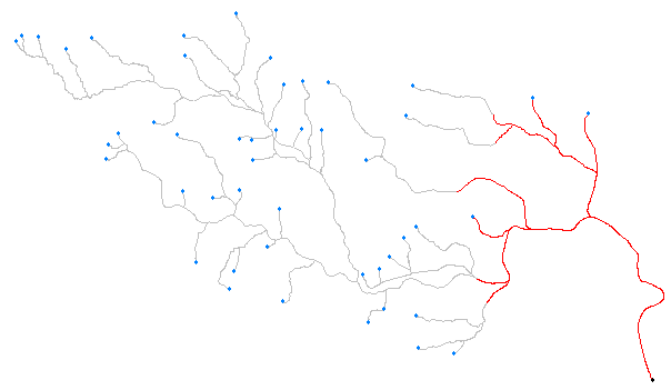
This is a river system. The data are given as lines representing river spans, and a point of the river mouth. Assume that the lines are edges of a complete network.

The goal is to extract river lines which are within the specified distance from the river mouth. Distance has to be measured along the lines.
The workflow consists of 3 parts.

Part 1: The two Snippers creates both end nodes of every river span (Snipping Mode: Vertex), and the Matcher selects end nodes of the network except the river mouth.

Part 2: The CoordinateExtractor extracts (x, y) of the end nodes, the FeatureMerger appends unconditionally every (x, y) to the river mouth (Process Duplicate Suppliers: Yes), and the 2DPointAdder is used to create line segments between the river mouth and every end node.


This image shows the end nodes and the line segments. These line segments will be used as FROM-TO lines for the ShortestPathFinder in the next part.


Part 3: The ShortestPathFinder finds shortest paths from the river mouth to each end node, the Snipper snips the paths into the specified length if the path length is greater than the specified length, and the PathSplitter and the Matcher are used to remove duplicated lines.


Red lines are the result. The river lines in the downstream have been extracted.


There are various exceptional conditions in the actual data, getting practical solution is not so easy. This is just a skeleton of the workspace.

2013-11-03

Advanced Geometric Operation: Create Normal Lines of a Line Segment

Create normal (perpendicular) lines against a line segment. Make the start node of the resultant lines be equal to the start node of the input line segment.
This image illustrates the expected result.


Workflow Example (FME 2013 SP4 Build 13547)
One possible approach is: offset the line segment so that its start node is located at (0, 0); rotate the line about (0, 0) by 90 (Left) / -90 (Right) degree; scale the lines into specified lengths; offset the scaled lines so that those start nodes are equal to the start node of the input line segment.
If the Scaler origin could be set to any location, the Offsetters would not be necessary. But options of the current Scaler origin are "0, 0" and "Center Point" only, so the workflow became cluttered a little.
A custom transformer which performs scaling based on specified origin coordinate can be created, and it might be useful to not only this workflow but also many scenarios.


Addition 2013-11-04: There is another approach using characteristics of unit vector and normal vector. This workflow looks more elegant and also efficient to me.


Application Examples:
These images were created with the workflow and several existing transformers.


The PythoCaller with this script can do the same operation as the workflow.
-----
# Example for PythonCaller (1): Create Normal Lines of a Line Segment
# FME 2013 SP4 Build 13547
# Assume input feature is a line segment; omit error handling.
import fmeobjects, math

class NormalLineCreator(object):
    def __init__(self):
        pass
        
    def input(self, feature):
        # Check geometry type and number of coordinates.
        if feature.getGeometryType() != fmeobjects.FME_GEOM_LINE \
           or feature.numCoords() != 2:            
            return # *** error ***
            
        # Extract coordinate of start node, offset feature,
        # and get length of the line segment.
        coord = feature.getCoordinate(0)
        feature.offset(-coord[0], -coord[1])
        lenS = feature.getGeometry().getLength(False)

        # Lengths of resultant normal lines.
        lenL = float(feature.getAttribute('_length_left'))
        lenR = float(feature.getAttribute('_length_right'))
            
        # Create resultant normal lines and output them.
        data = [('left', lenL / lenS, 90.0), ('right', lenR / lenS, -90.0)]
        for direction, scale, angle in data:
            line = feature.clone()
            line.rotate2D((0.0, 0.0), angle)
            line.scale(scale, scale)
            line.offset(coord[0], coord[1])
            line.setAttribute('_normal_direction', direction)
            self.pyoutput(line)
            
    def close(self):
        pass
-----
# 2013-11-04
# Example for PythonCaller (2): Create Normal Lines of a Line Segment
# FME 2013 SP4 Build 13547
# Assume input feature is a line segment; omit error handling.
import fmeobjects, math

class NormalLineCreator(object):
    def __init__(self):
        pass
     
    def input(self, feature):
        # Check geometry type and number of coordinates.
        if feature.getGeometryType() != fmeobjects.FME_GEOM_LINE \
           or feature.numCoords() != 2:          
            return # *** error ***
     
        # Calculate unit vector of the line segment.
        seg = feature.removeGeometry()
        start, end = seg.getPointAt(0), seg.getPointAt(1)
        (x0, y0, z0), (x1, y1, z1) = start.getXYZ(), end.getXYZ()
        lenS = seg.getLength(False)
        ux, uy = (x1 - x0) / lenS, (y1 - y0) / lenS
     
        # Transform the feature to the start node point.
        feature.setGeometry(start)
     
        # Lengths of resultant normal lines.
        lenL = float(feature.getAttribute('_length_left'))
        lenR = float(feature.getAttribute('_length_right'))
     
        # Create resultant normal lines and output them.
        data = [('left', lenL, -uy, ux), ('right', lenR, uy, -ux)]
        for direction, len, nx, ny in data:
            line = feature.clone()
            line.addCoordinate(x0 + nx * len, y0 + ny * len, z0)
            line.setAttribute('_normal_direction', direction)
            self.pyoutput(line)
         
    def close(self):
        pass
-----

2013-11-01

FME 2013 SP4 has been upgraded

Current newest Build Number is 13547, it's now downloadable.
The bug on max / min function (FME Math Functions) has been fixed.
Community > ExpressionEvaluator Answer Changed